PPG Heart Rate Sensor
Electrical Lead
Jan 2026 - Apr 2026
Overview
Photoplethysmography (PPG) is the same optical technique used in smart wearable devices to measure heart rate. An infrared LED shines light into the skin, and with each heartbeat, blood volume in the tissue changes slightly, which changes how much light bounces back to the photodiode. That small signal goes through a circuit chain to extract useful heartbeat information.
I designed and built the complete analog signal chain, amplifying the raw photodiode current, filtering it down to the cardiac frequency band, converting the waveform into a clean digital pulse, and finally driving an LED that flashes with each detected heartbeat.
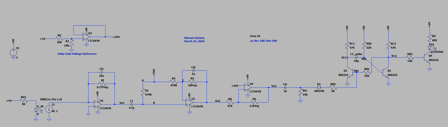
Signal Chain
The challenge with PPG is the signal-to-noise problem. The photodiode produces a roughly 1 µA DC current from ambient IR reflection, with the actual heartbeat being a ~0.1 µA ripple. The circuit chain is broken into 5 stages to handle this:
- Transimpedance Amplifier: converts the photodiode's tiny current into a measurable voltage using high resistance feedback.
- Bandpass Filter & Gain: strips out the large DC offset with a high-pass filter, then amplifies the remaining heartbeat signal ~20x. A low-pass cutoff rejects high-frequency noise. The bandpass filter allows frequency in the range of ~200mHz (high pass corner frequency) to ~12Hz (low pass corner frequency). Although the human heartbeat is well within that range, a higher bandwidth was chosen to be able to capture higher order harmonics.
- Schmitt Trigger Comparator: converts the analog waveform into a clean digital pulse. Hysteresis band (implemented with feedback) prevents noise near the threshold from causing false triggers.
- Monostable Multivibrator: triggered by the rising edge of each comparator pulse. It holds its output high for a fixed duration set by an RC time constant, ensuring one consistent pulse per beat.
- LED Driver: a transistor switch that turns on the indicator LED for the duration of the monostable's output pulse. This results in an LED blink per heartbeat.
Design Process
I designed the pipeline described above to do this. After calculating the component values and gains, I systematically implemented and tested each stage in LTSpice to validate the design.
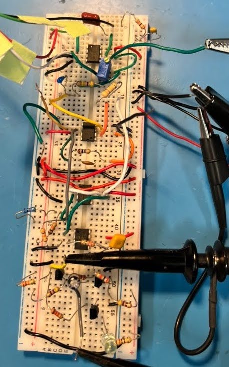
 After slightly tweaking the component values, I prototyped it on a breadboard.
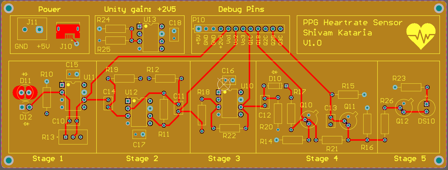
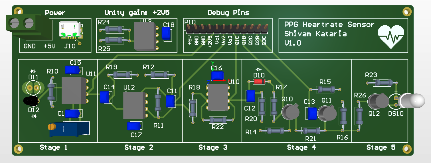
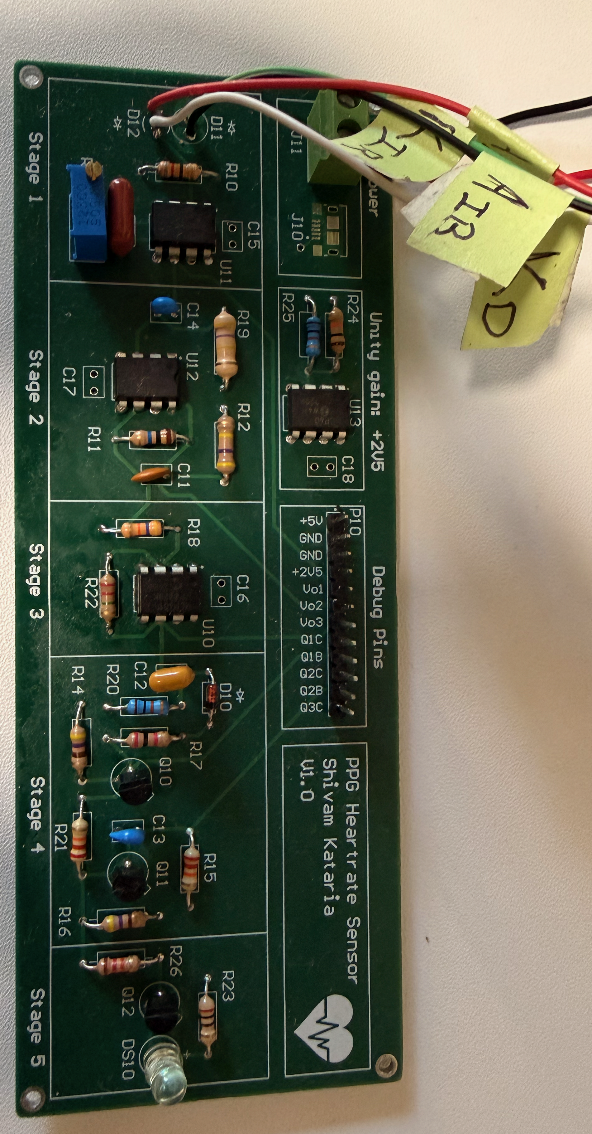
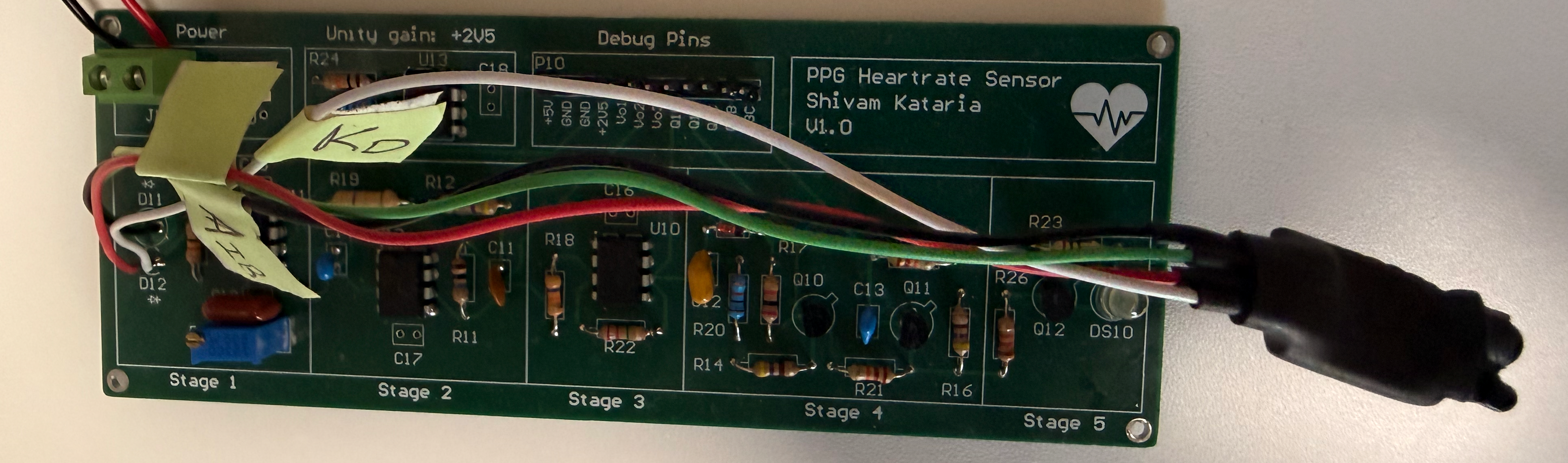
PCB Design
After validating the circuit on a breadboard, I created a 4-layer PCB for the design. Moving off the breadboard improved signal integrity as the traces were shorter, and there were interrupted ground and power planes to reduce coupling. This PCB was meant for an organized visualization of the circuit, with the goal being clarity rather than miniaturization.
 View PCB Schematic (PDF)
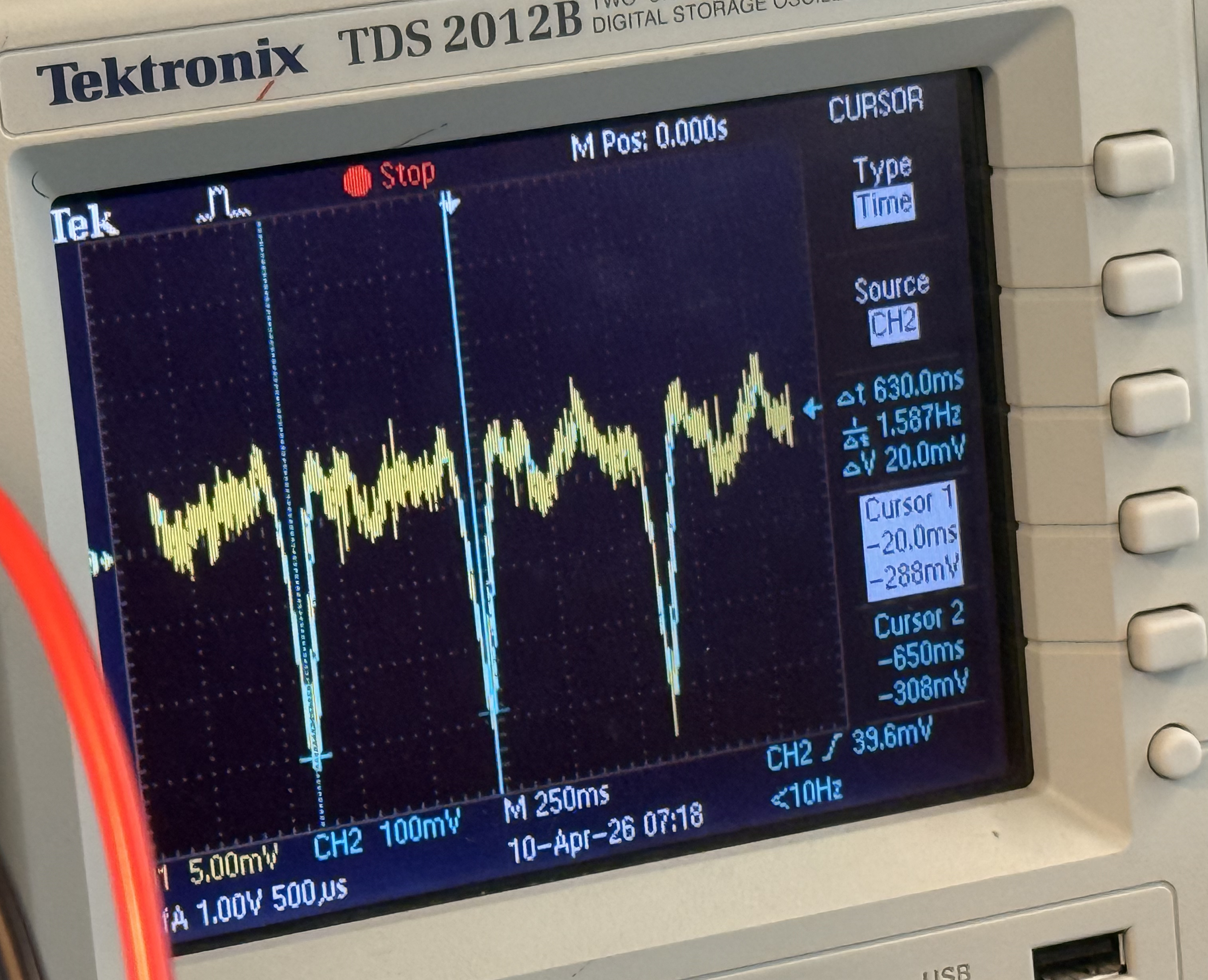
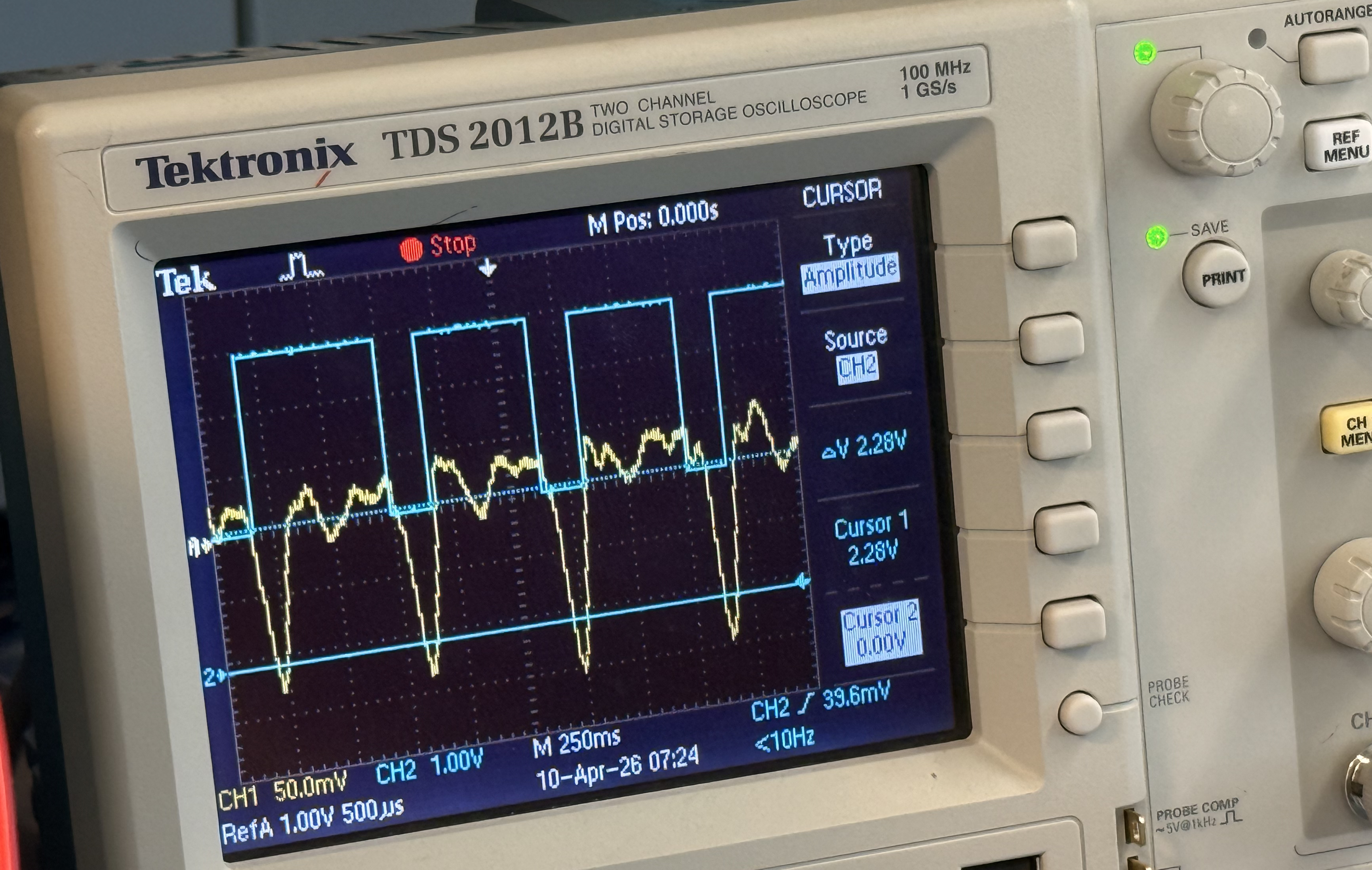
Results
The completed circuit successfully detects a pulse from a fingertip or wrist placement, producing a clean digital output that flashes an LED once per heartbeat. Measured heart rate was validated with a wearable device reading to ensure correctness, and the comparator output showed no false triggers under normal conditions.
Future Improvements
The project was a good lesson in the practical difficulty and consideration required for extracting biosignals. In the future, I would like to miniaturize the design and integrate it into a wearable form factor. Potentially also making it a smart device which syncs the data with a mobile app.